


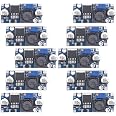
10 Pack LM2596 DC-DC Buck Converter Step Down Module Power Supply DIP Output 1.25V-30V 3A
Details
- BrandBULVACK
- Power SourceCorded
- Mounting TypePCB Mount
- Current Rating3 Amps
- Item Weight4.6 Ounces

Description
🔧 Power Your Projects with Precision!
- PREMIUM COMPONENTS - Crafted with SANYO solid capacitors and high-Q inductors for superior durability.
- HIGH EFFICIENCY DESIGN - Maximize performance with a robust 3A output current, ensuring reliable power delivery.
- VERSATILE VOLTAGE RANGE - Input voltage from 3.2V to 35V, perfect for diverse applications.
- PRECISION OUTPUT CONTROL - Continuously adjustable output from 1.25V to 30V for tailored power solutions.
- USER FRIENDLY INDICATORS - LED indicator for real-time monitoring of power status.
The 10 Pack LM2596 DC-DC Buck Converter Step Down Module offers a versatile input voltage range of 3.2V to 35V, with a continuously adjustable output from 1.25V to 30V and a maximum output current of 3A. Built with high-quality SANYO solid capacitors and thick circuit boards, this module ensures high efficiency and reliability for all your power supply needs.
Have a Question? See What Others Asked
Reviews
T**Y
Stable, good quality, affordable variable dc-dc bucks
I saw other reviews complaining of DOAs, but took a chance on a 10-pack.I have opened and tested 4 of them and have seen no issues at all. They work as intended. Other reviewers are correct to start turning the adjustment CCW for several turns and you will see the voltage drop.These are not bidirectional; they will not boost voltage, only attenuate. Minimum differential is about minus 1.5volts between the input and outputs.
H**P
Awesome little converters
Bought these to use with my 3d printer and Octopi, turns out they work well at converting solar too. The little buck converter steps down the 18V-22V solar panel and keeps the voltage at a constant 5v to charge my Ring doorbell. It was a pain to have to take the door bell in the charge every few weeks. Been about 2 months since I put this in and it is still going strong. I used a spare solar panel laying around for this, recommend using a much smaller solar panel as this one only takes about 1.5 hours of indirect sunlight to fully charge the doorbell from 85% to 100%. Do not put this size solar panel directly in the sun for this project.
S**N
Small And worked beautifully
Easy to hide in boxes and assemblies and worked beautifully as 5v to lower as LED dimmers.
D**R
Buck converter works well but needs an additional capacitor to lower the high ripple voltage.
These work well. However have very high ripple voltage .. over 100 mV, and need about 1000uF added to the output to be acceptable.
P**G
Low Power Considerations
Summary:- Drops 14-12v to 6.5v and holds the output at the set point across that range.- This board is cheaper than the switching voltage regulator component alone.- Can it really be an authentic LM2496S - who knows, do we care?- Basic reference circuitry with an adjustable potentiometer - right for more, left for less.-- For fixed applications (like mine) you could nuke that pot and slap in a fixed value resistor.- For low power functionality - delete the LED and 102 (1,000 Ohm) resistor.-- You'll lose the 'on' indicator LED and its companion resistor, but Ohms law doesn't lie.-- Post operation, no load power use dropped from 0.010A to 0.007A - no puns, that's a 30% improvement.- Dodging name brand over pricing.- There are probably better ways to do this, don't be hatin'.Using this device to step down 14-12v to 6.5v to power remote trail cameras with slightly more available 12v deep cycle batteries vs the 6v alternative. Testing on the bench, no-load showed this device was capable of performing as advertised. I don't have a scope so I can't comment on output noise, still chunked a MLCC (better capacitor) on flipside of the board across the existing output cap - it was 'used' so whatever, gave myself an 'E' for low-ESR. - I'll digress.Generally speaking it makes sense from a user/support perspective to go with the manufacturer 'name brand' accessories for these remote units. But I couldn't resist the penny pinching backside of mine to not go DIY on this one - and you'll see why if you choose to hang in here for another paragraph (or so).For a quantity of 10x at this time, these boards are $1.35/each - the LM2596S alone, is $2.50+ component from the component superstores mouser or digi-key. Most likely this is a ghost shift LM2596S, thank you (big semiconductor corp here) for doing business with China and/or letting the design slip, now I'm doing business with them. I only feel slightly guilty, but you're a bunch of penny pinching trolls too so don't even.Now that the ethics, China, and money bag corporation rants are set aside my fiscal justification for going this route:- OEM part (connectors, cable, regulator, and plug) cost $14.99+TAX- This part, some janky-as copper clad aluminum cable, and the wrong sized plugs resulting in a direct connect plus battery spades, cost <$3.00/each.Most likely the OEM did the same thing, but with some ill volume discounts, meaning they're taking your $12 after materials straight to the bank.Keeping my $12, doing this thing - forgot to indicate - yes the battery side will be fused, I don't need a big-as forest fire on my conscience.
D**M
Good value
I powered two of these so far and as the other users state it takes many turns to get down to 1.5 to 5 V. At low power these will run discontinuous and generate a noisy output that causes the reading on my Fluke DVM to be unstable. TI recommends some kind of filter where a clean output is needed. Adding a 1 ohm resistor in series with a 47 uF 16 V tantalum caused the DVM readings to stabilize.A second concern is the ability of the power source to stand up to the switching current. This device comes with a 100 uF 50V aluminum capacitor on the input which is rather small. When powering from a transformer, rectifier and filter the capacitor must be large enough to keep the 120 Hz ripple low. During most of the 8.3 msec cycle only the filter capacitor is providing current. I recommend the green high frequency low ESR kind for this switcher to draw from. For a 1.5V output I powered from a 7.5 V DC input from a puny 12 Vct 0.5 A transformer. I needed 10,000 uF to hold up the input voltage at 2 A load. As the input voltage drops a buck converter will draw more current, causing 120 Hz ripple to increase to the point the buck converter stops working. A 2200 uF capacitor could not deliver 2 A load.
G**S
Handy for homebrew projects
These things supply a reasonable amount of current with a moderate amount of ripple. Easily adjustable to the right voltage, and doesn't sag under reasonable load.
Common Questions
Trustpilot
2 weeks ago
2 months ago
